

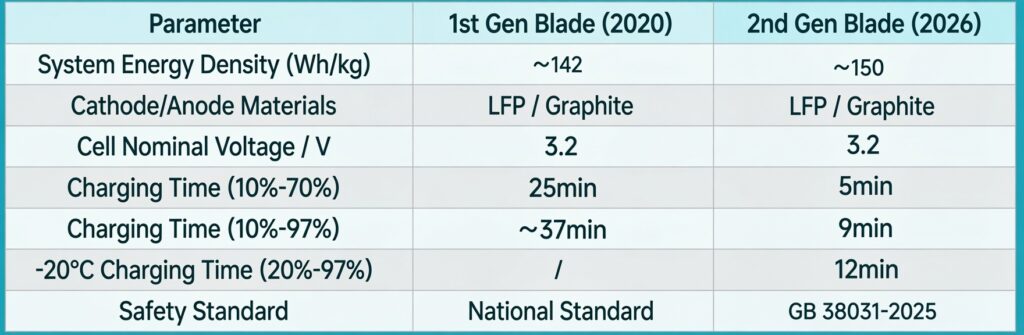
01 Comparison of Gen-2 Blade Battery Specifications
BYD second generation Blade battery is the subject of intense technical discussion online.In response to ongoing online discussions about the technical parameters of BYD’s second-generation Blade battery (short-blade), this section provides a detailed analysis of two key points:
1) System Energy Density
According to the MIIT (Ministry of Industry and Information Technology) filing data for the Denza Z9 GT, its battery pack has a nominal capacity of 122.5 kWh and a total mass of 862.4 kg, yielding a system-level energy density of approximately 142 Wh/kg. Combined with BYD’s official disclosure that “the second-generation Blade battery’s system energy density has improved by more than 5% over the first generation,” it can be estimated that the optimized second generation reaches approximately 150 Wh/kg.
2) Cathode Material
By dividing the total battery pack voltage shown on the vehicle’s nameplate by the number of cells connected in series, the per-cell voltage is approximately 3.2 V, indicating that the cathode material remains lithium iron phosphate (LFP).
02 Battery Pack Structural Teardown
1) Overall Composition
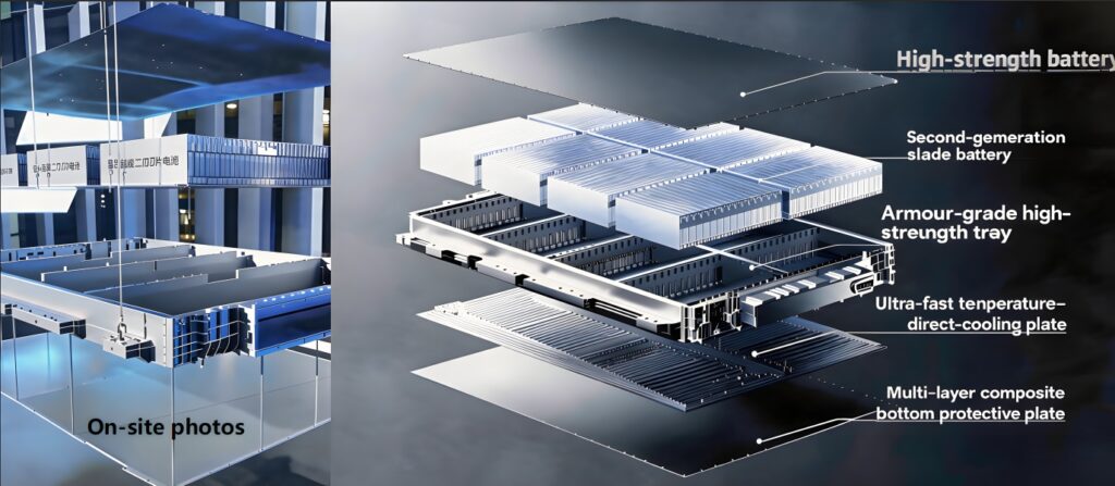
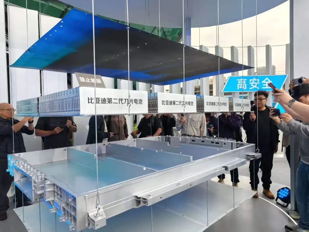
The second-generation Blade battery pack consists of a high-strength battery top cover, second-generation Blade cells, armor-grade high-strength tray, ultra-fast direct cooling plate, and multi-layer composite bottom shield, forming an endoskeleton-style high-safety structure that balances protection, thermal management, and structural integrity.,Figure 2 shows an exploded view.,Figure 2-2 is a photograph I took on site at BYD’s official second-generation battery exhibition hall.
2) Busbar Design
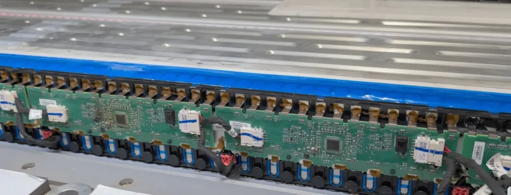
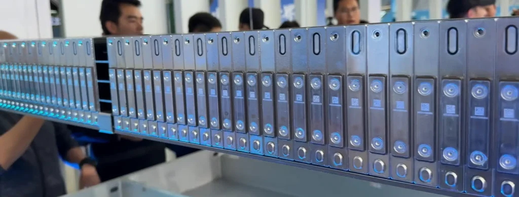
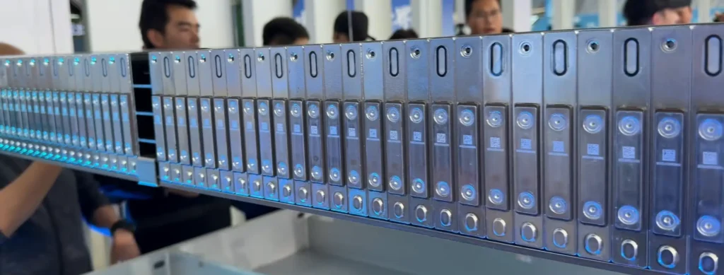
A notable difference between BYD’s first- and second-generation Blade batteries is the busbar layout inside the pack: the first generation places busbars on both the left and right sides, while the second generation relocates them to the center.
Figure 3 shows a photograph I took whilst visiting the site and dismantling the first-generation blade battery.
Figure 3-1 and Figure 3-2 I took these photographs of the second-generation Blade Battery at the official BYD exhibition hall.
3) Cell Design
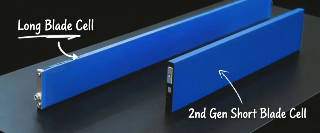
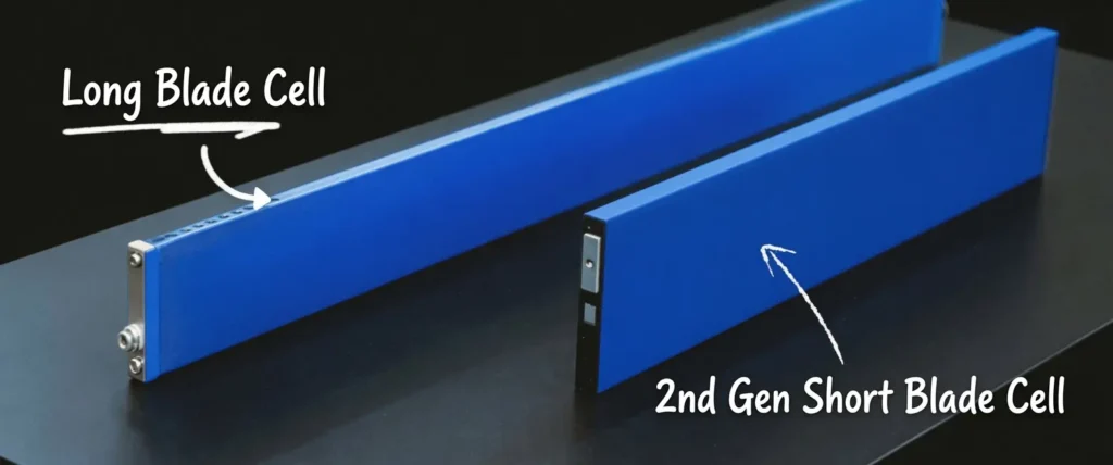
The second-generation Blade battery features an upgraded short-blade cell design with shortened cell length and widened terminal cross-section. The first generation routes terminals from the same side, while the second generation routes them from both sides.For further details, please see the actual photographs below (Fig. 4).
03 Why Does the Gen-2 Blade Battery Charge So Fast?
Lithium-ion battery charging is typically divided into two phases:
- Constant Current (CC) Phase: When the state of charge is low, the battery can accept very high currents.
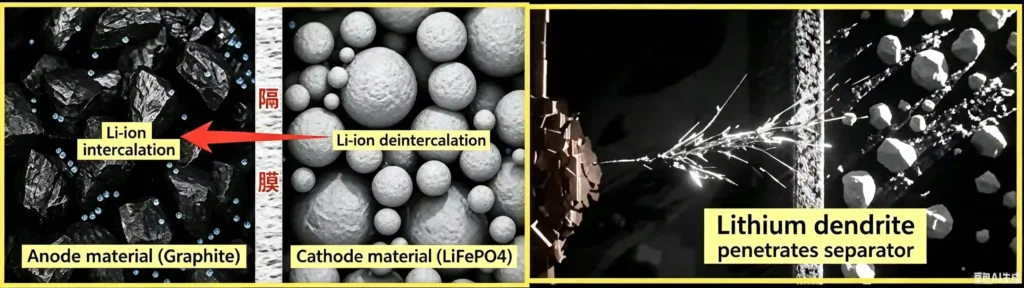
- Constant Voltage (CV) Phase: Once charge exceeds 80%–90% and the CV phase begins, large numbers of lithium ions crowd into the interlayer structure of the graphite anode, causing polarization voltage to rise rapidly. To prevent overvoltage from preventing lithium-ion intercalation — which would cause metallic lithium dendrites to precipitate on the anode surface — the BMS must forcibly limit current and extend the constant-voltage float-charging time. As a result, the last ~20% of charging often takes as long as the preceding fast-charge segment, forming an insurmountable electrochemical barrier.
As noted in the Blade battery characteristics above, the underlying crystal structure of the second-generation battery has not undergone a fundamental change compared to the first generation (energy density is constrained by the material’s crystal lattice). So how is BYD flash charging achieved within the existing LFP system?
1) Battery Side — Reducing Resistance
The core of fast-charging technology lies in “resistance reduction” — the second-generation Blade battery constructs a “high-speed channel” for lithium-ion migration, significantly lowering internal resistance and suppressing Joule heating at the source.
The cell form is upgraded to a “short-blade” design: by shortening the cell length and increasing the terminal cross-sectional area, the geometric path impedance of electron conduction is drastically reduced, achieving extreme compression of ohmic internal resistance at the physical level.
At the pack level, a “central busbar” layout replaces the traditional “dual-side busbar” configuration: while reducing weight and cost, this design shortens the current loop and simplifies connection nodes, substantially lowering system contact resistance and internal resistance, and creating a low-impedance transmission channel for megawatt-level charging currents.
2) Grid Side — Flash Charging Stations
To achieve high-rate, short-duration energy replenishment while avoiding thermal runaway and lithium plating risks, a comprehensive effort spanning from microscopic materials to the macroscopic power grid is required. How can the grid capacity crisis be solved to enable megawatt-level flash charging?
04 How Is Flash Charging Achieved at -30°C?
The extreme cold-weather charging performance demonstrated by the second-generation Blade battery breaks through the inherent constraints imposed by the Arrhenius equation in chemical reaction kinetics on the low-temperature performance of traction batteries. Conventional LFP batteries, at temperatures of tens of degrees below zero, experience a dramatic spike in electrolyte viscosity and a cliff-like decline in ionic conductivity; at the microscopic level, the cell is nearly in a state of ionic conduction blockade. If high-power charging is forced under these conditions, severe lithium plating side reactions can be instantly triggered. The industry has traditionally relied on external PTC ceramic heating solutions, but this external-to-internal heat conduction mode is highly inefficient, creates excessive temperature gradients between the cell’s interior and exterior, and causes severe long-term damage to battery life.
1) All-Scenario Intelligent High-Frequency Pulse Self-Heating Technology
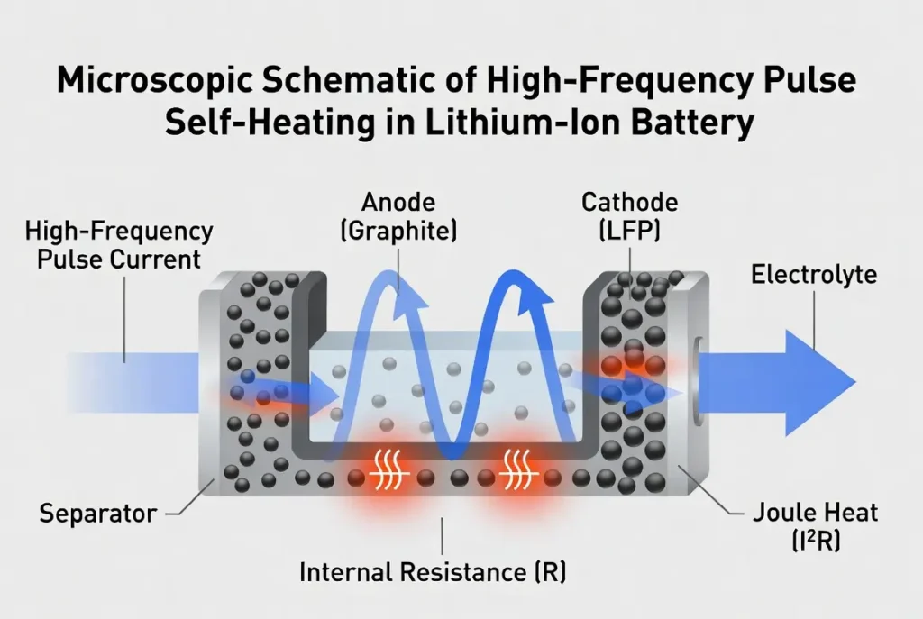
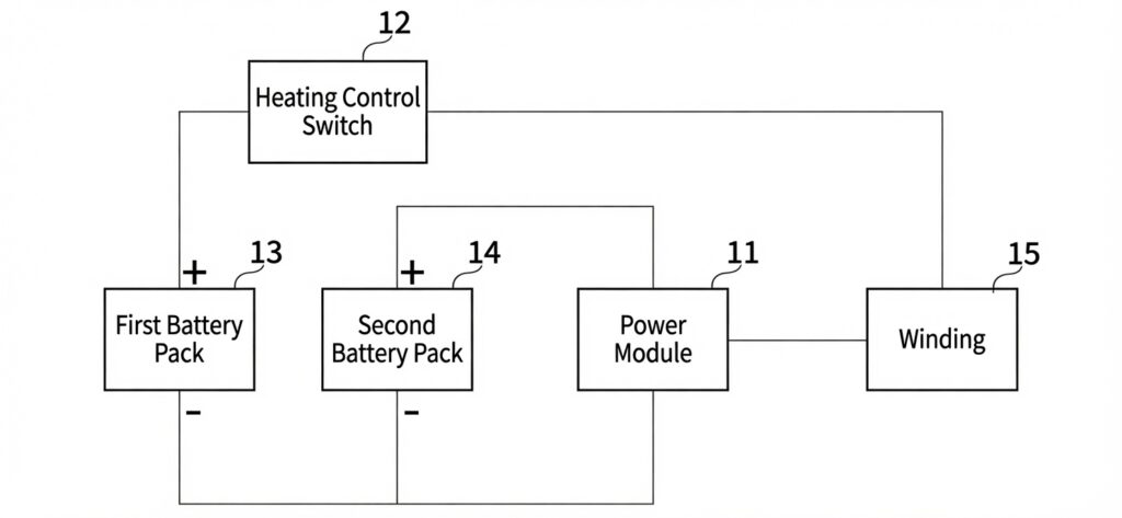
The core principle of this technology relies on the cell’s own ohmic and polarization internal resistance. The Battery Management System (BMS) controls the injection of high-frequency alternating current into the cell, driving lithium ions to undergo high-frequency micro-amplitude oscillation between the cathode and anode. Through ion-level violent collisions and friction, heat is generated from within the cell, achieving self-heating.
2) Single-Layer Direct Cooling Plate Design
During ultra-high-current fast charging, heat generation within the Blade battery is not perfectly uniform — the massive heat is concentrated primarily at the positive and negative terminal regions at both ends. The Gen-2 Blade battery’s direct cooling plate, through a specially designed circuit tube configuration, precisely concentrates the maximum heat dissipation and cooling efficiency at the head and tail ends of the flow path.
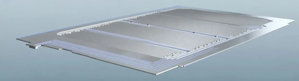
BYD’s second-generation Blade Battery with a single-layer direct-cooling plate structure,Image source: BYD official website